
Draft. This manual is new and still growing. If something here does not match what you see in the software, the software is right — tell us and we will fix the page.
Build and repair geometry in the Geometry workbench
The Geometry ribbon tab is a workbench of its own: primitives, transforms, repairs and the B-rep operations, with a feature history down the left. This page is what ships in it, where each command is, and where its result goes.
Importing a file and splitting it into patches is its own guide. This one starts after that.
Runs on the free tier.
Two rows called Geometry, and only one of them imports
The setup tree has a Geometry row at the top, above the studies, and another Geometry row inside each study. They open the same pane showing different halves of it.
- The case's row — depth zero, above every simulation — owns the body: Import, Units, Heal on import, Aerofoil extrusion, Parts, Display, Geometry info and Supported formats.
- A study's row — indented under the simulation — carries one control, Domain, which picks which of the case's geometries this simulation runs on. Nothing else, because nothing else is a property of the study: importing, healing and splitting change the body for every study at once.
With one geometry in the case the Domain combo still appears, with one entry, and the study's row says so: "This case has one geometry. Import another on the case's Geometry step and each simulation can run on whichever it needs." That sentence is the tell that you are on the study's row rather than the case's.
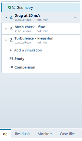
When several geometries are in the case they are listed as children of the case's row and clicking one loads it. With a single geometry that list is not drawn.
Getting into the workbench
Pick the Geometry tab in the ribbon. Picking a tab switches the workbench, so the scene tree is replaced by the feature history and the ribbon by the CAD commands.
The tab is not always usable, and this is the thing to know before anything else: it is enabled while the case's geometry is still CAD, and on a case that has no body yet. What closes it is a geometry that has become a mesh. Hover the tab and it tells you which state you are in — "Sketch and modify the geometry", or "Start a shape here - Primitives builds a box or a cylinder from nothing" on an empty case, or, struck through, "Sketching and CAD operations need imported CAD, not a mesh".
Three consequences, all worth planning around:
- A case whose geometry is an STL, OBJ or any other triangle format never reaches this workbench.
- An empty case does reach it, which is how CREATE → Primitives builds a model from nothing when there is no CAD to import.
- On a fluids case, Translate to triSurface replaces the case's geometry with the STL the translator wrote, and the family becomes a mesh — so the Geometry tab strikes out the moment you translate. Do the geometry work first, then translate.
Leaving the workbench is the tab strip again, or Done editing at the foot of the feature list.
What the ribbon holds
Five groups. Two commands are both called Delete, which is why these pages name a group as well as a command.
| Command | What it is for |
|---|---|
| Geometry → CREATE → Flow volume | The fluid volume: a box with the model subtracted out of it |
| Geometry → CREATE → Primitives | Add a box or cylinder to the model |
| Geometry → FACE → Delete | Remove faces, healing or capping the hole |
| Geometry → BODY → Delete | Remove whole selected bodies from the geometry |
| Geometry → BODY → Close sheet | Close a surface that is missing faces |
| Geometry → BODY → Facet split | Split a mesh into faces by angle |
| Geometry → BODY → Imprint | Cut shared interfaces between touching bodies |
| Geometry → BODY → Scale | Resize the model by a factor |
| Geometry → BODY → Split | Cut the model with a plane and keep one side |
| Geometry → BODY → Boolean | Union, subtract or intersect overlapping bodies |
| Geometry → BODY → Transform | Translate or rotate the model |
| Geometry → BODY → Simplify | Replace a detailed body with a box or cylinder |
| Geometry → MODEL → Fix interferences | Subtract overlapping volumes automatically |
| Geometry → MODEL → Add CAD | Add another imported model to this one |
| Geometry → TOOLS → Gaps | Find gaps narrower than a tolerance |
| Geometry → TOOLS → Interferences | Find bodies that overlap |
Four more are listed and permanently greyed: FACE → Move, FACE →
Extrude, BODY → Improve (badged ALPHA) and BODY → Wrap.
They are drawn rather than hidden so that the set of operations is visible;
hovering gives the reason, which is either "This build has no B-rep geometry
kernel…" or, where the translator is present, "The geometry kernel is present,
but this operation is not implemented yet." Do not plan a workflow around them.
Flow volume is the external one — a box with the solids cut out of it, which
is a virtual wind tunnel, and its two fields are Box minimum and Box
maximum. There is no internal-volume extraction. A duct's inside is meshed by
setting the mesher to blockMesh only (no body) on the Mesh step instead.
Running an operation
- Click the command. Its settings panel opens beside the feature list, headed with the command's own name.
- Fill in the fields. They are declared per operation, so the panel shows only
what that command takes, and a choice that switches shape hides the fields
the other shape uses — picking
Boxon Primitives hides Cylinder centre, Cylinder axis, Radius, Height and Segments. - Where a field is a selection — Faces to delete, Bodies to delete,
Target bodies, Bodies to imprint — pick the entities in the viewer or
the scene tree. The count appears in the label and each entity is listed
underneath by name, with a ✕ to drop one and Clear list to drop them
all. Names come from the CAD's own topology where it has one, so the panel,
the tree and the viewer all say
Face 7 (cylinder)rather than three different numbers. - Press Apply. Cancel, and the ✕ in the panel's header, both close it without doing anything.
Apply is inert until the operation can run, with the reason in amber above it:
- "Nothing imported to operate on." — there is no geometry. Primitives is exempt from this, deliberately: it is the one command that creates geometry, so requiring geometry first would be circular.
- "Select the faces in the viewer or the scene tree." (or "bodies") — nothing is selected.
- "Switch the viewer to Select faces - this works on faces, not whole bodies." (or the converse) — something is selected, in the wrong mode.
Starting a case from a primitive
The one path that begins from nothing:
- Geometry → CREATE → Primitives.
- Set Shape to
BoxorCylinder, then Box minimum and Box maximum, or Cylinder centre, Cylinder axis, Radius, Height and Segments. - Apply.
On an empty case the shape is written out as an STL into the scratch directory and imported, so it becomes the case's geometry exactly as a file would: it appears in Geometry info, it meshes, and the case adopts a copy when it is saved. On a case that already has a body, the primitive is added to that body instead.
Checks that only report
Gaps takes a Maximum distance in metres; Interferences takes nothing. Both write to the Log in the bottom dock — "No gaps found below 0.001 m", or a line per pair naming the two bodies and the distance or the overlap volume — and neither records a feature, because a history of things that did not happen is noise.
The feature history
The left panel lists GEOMETRIES, the source file, and every operation applied to it, oldest first. Before there is one it reads "No edits yet — pick an operation above."
- Clicking a feature toggles it. A disabled one is dimmed and skipped.
- The ✕ on a feature removes it.
Either one replays the list from the start, which is what makes a CAD edit reversible: the source file is never written to, so removing a feature and replaying gives the model as it was before that edit.
The replay is also where the two kinds of operation part company. The B-rep ones — Flow volume, Boolean, Fix interferences, Imprint and FACE → Delete — are defined on the CAD's own faces and solids, so they are recorded and handed to the OCCT translator, which re-reads the original file with them applied. Everything else acts on the tessellation the viewport is holding. Taking a B-rep command on a geometry that is already a mesh is refused in the Log: "CAD: … needs a CAD model - this geometry is a mesh, which has no faces or solids to operate on."
Note what the second kind does not do. The body handed to the mesher is
written from the imported file, so a Scale, Split or Transform
changes the viewport and the feature list without changing what lands in
constant/triSurface. To resize the model for the case, set Units on the
case's Geometry step — that is applied when the geometry is read.
Named regions are somewhere else
Geometry primitives, the tree row under each study's Geometry, is not this. Those are named boxes, spheres, cylinders and points that mark out a piece of space for something else to point at — a refinement region, an initialisation subdomain, a probe location — and they are not part of the model. CREATE → Primitives builds a body.