
Draft. This manual is new and still growing. If something here does not match what you see in the software, the software is right — tell us and we will fix the page.
External aerodynamics on a body
At the end of this you will have a converged three-dimensional drag and lift result on a real body, a mesh you refined deliberately rather than by accident, and a report that splits the drag into the part caused by pressure and the part caused by friction.
The workflow runs on the free tier; a mesh you would defend in a review will not. Nothing here is gated by physics — free carries every analysis type and every boundary condition — but a 3-D body with refinement in the wake and a properly resolved boundary layer wants more cells than the 250,000-cell cap, and the moment you add your own refinement region the estimate will go over it and the Problems tab will say so. Where that happens is called out below.
Before you start
Read Flow over a cylinder. This tutorial assumes you have meshed something and watched residuals before.
Start from the bundled example. On the home screen, press
Worked example and choose External aerodynamics - streamlined hull. It
opens with the bundled hull in a 20 m/s air stream and — importantly — three
simulations already in the case rather than one: Drag at 20 m/s,
Mesh check - fine and Turbulence - k-epsilon.
Everything below applies to your own geometry too. Substitute Import geometry under Geometry for the example's hull and the steps do not change.
Commands are on the ribbon, in three tabs. On the Model tab, Generate mesh and Quality are in the MESH group, Start run and Continue in RUN, and Comparison and Report in STUDY. Selecting a Post-processing row switches the ribbon to the Results tab, whose groups are FILTERS, VIEW, COMPARE, CAPTURE and RESULT.
1. Geometry
Select Geometry — the row at the very top of the tree, above the simulation headings. There are two rows with that name, and only this one carries Import, Units, Heal on import, Split into parts and the Geometry info block; the row under a simulation only picks which of the case's bodies that simulation runs on.
Read the Geometry info block before anything else, because two of its rows decide whether the rest of the case is meaningful.
Watertight must say yes. snappyHexMesh works by deciding which side of
your surface is inside and which is outside; a surface with open edges gives it
no way to answer, and the mesh leaks into the body. If it says open edges,
turn on Heal on import and re-import, and fix it in CAD if that does not
clear it.
Frontal area is the number every force coefficient will be divided by. It is computed from the geometry against the flow direction. If it is wrong — because the body is oriented differently from what you assumed, or the units were wrong on import — then Cd is wrong by exactly that factor and nothing else will complain.
Splitting the body into parts
If your geometry is modelled as several bodies — a hull and its control surfaces, an assembly, a manifold — press Split into parts. Each becomes its own patch, with a Patch name field you can edit and a count of triangles and area beside it.
This matters because a force can then be asked about one component instead of the whole thing. Each part carries a Measure force and moment on this part button, which creates the matching item under Result control and takes you there.
Merge back into one patch undoes it.
2. Mesh
Select Mesh.
Flow direction does more than it looks. Its hint lists the four things it sets: the reference length and frontal area, the wind-tunnel pads, the inlet and outlet patches, and the drag direction. Get it wrong and the drag you compute is a side force.
Incidence α and Sideslip β apply the angle to the oncoming flow rather than to the body. That is deliberate and it is what lets a sweep reuse one mesh: run the same case at a few angles and the coefficients become curves. Lift and drag are then resolved along the tilted stream, not along the tunnel axis. Leave both at zero for now.
Auto wind tunnel sizes the block from the geometry bounding box in multiples of body length. The five pads are asymmetric by default and should be: the wake pad is much larger than the ahead pad, because the wake is the part of the domain that has something in it. Shrinking the wake pad is the fastest way to make a drag result quietly wrong — the outlet ends up inside the recirculation.
Base cell size sets the background block. Press Suggest from domain for a starting value scaled to the box, then read the block below:
→  … x … x … m
    blockMesh … x … x … = … M cells
That is the background alone, before any refinement.
3. Refinements — where the cells actually go
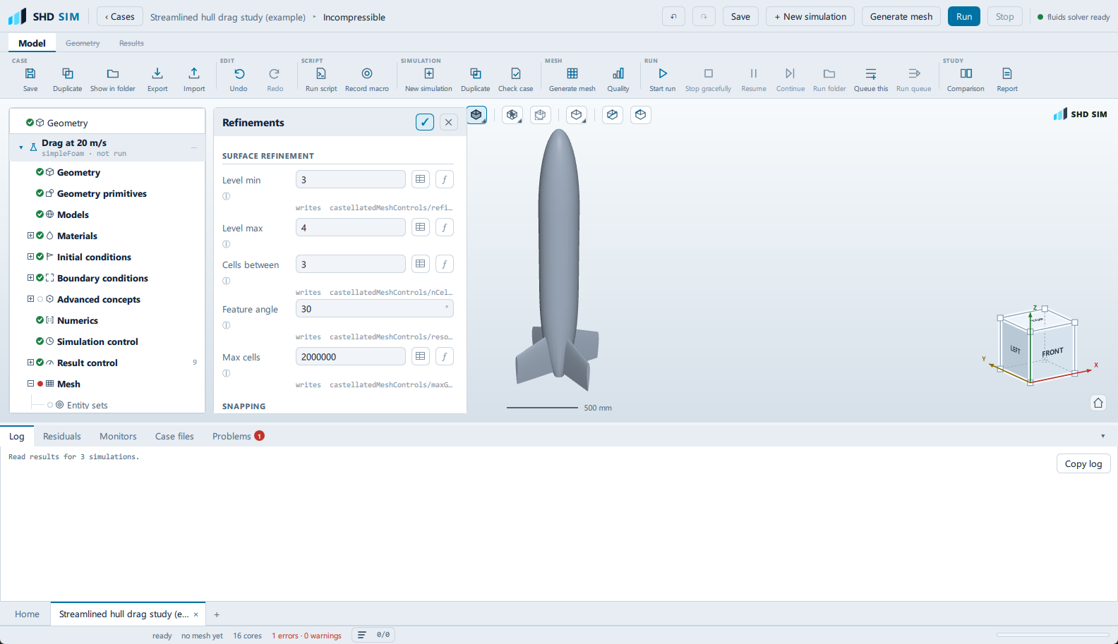
Select Refinements. This is the pane that decides whether the mesh is any good.
Surface refinement
Level min is the level every cell touching the surface reaches. Level max is reached only where the surface curves more sharply than the feature angle. Each level halves the cell size, so the difference between level 3 and level 5 is a factor of four in cell size and a large multiple in cost.
Cells between is the buffer of cells between one refinement level and the next. Higher is smoother and gives better quality at more cells. It is the cheapest quality improvement available and the first thing to raise if Quality is unhappy.
Max cells is a hard budget: refinement stops when it is reached, so the mesh may simply not achieve the levels above it. On the free tier set this to 250000 or below — it defaults to 2,000,000, and leaving it there means the Problems tab blocks the run after you have waited for a mesh.
The block underneath tracks the consequences as you type:
→  base … m   surface … m
    estimate … M cells
Refinement regions
This is the section the tutorial is for. Surface refinement puts cells near the body; a refinement region puts cells in a volume, which is how a wake gets resolved. Without one, the wake is meshed at the background cell size and dissipates within a body length of the body — and a dissipated wake gives an optimistic drag.
Press + Add refinement region. A card appears with:
- Shape —
boxorsphere. - Mode —
insiderefines within the shape,outsiderefines beyond it,distancerefines within a given distance of the surface. - Level — the refinement level inside the region.
- Ahead, Wake, Sides, Above, Below — for a box, the pads in body lengths off the geometry bounding box, exactly as the domain pads work.
For a wake box, keep Ahead, Sides, Above and Below small and set Wake to cover the length of wake you care about. Set Level one below your surface Level min — a wake box at the same level as the surface costs enormously and resolves nothing you need.
Each card has enable / disable without deleting it, and ✕ to remove it. Disabling is the better move while you are hunting for a cell budget, because it keeps the region for later.
Watch the estimate as you add it. A region fills a volume rather than coating a surface, so it usually dominates everything else in the mesh. This is where the free cap bites, and it is not a bug: a resolved wake on a 3-D body is a bigger mesh than 250,000 cells.
4. Boundary layers
Select Boundary layers.
The pane works forwards from what you know. You give it Target y+; it gives you the first-layer height, because nobody thinks in first-layer heights.
→  Re …  at … m/s, L … m
    first layer … m
    total thickness … m
    surface cell … m
Target y+ must agree with Wall treatment under Models, and the hint here changes to match: wall functions want y+ between 30 and 300; resolved low-Re treatment needs y+ of about 1. Disagreement between the two is the most common way a turbulence model gets misused, and it produces a plausible answer.
Layers is the number of prism layers, Expansion the ratio between successive ones. The hint gives 1.1 to 1.3 as the useful band: higher reaches the surface cell size in fewer layers but grows the aspect ratio.
Two warnings appear here and both are worth obeying:
- The layer stack is as thick as the surface cell. The outermost prism then sits against a cell much larger than itself. Reduce Layers or Expansion, or refine the surface further.
- First-cell aspect ratio … is high. Usually tolerable inside a layer stack, but watch the linear solver.
After meshing, the Coverage block reports what was actually achieved on the
body patch. Below 70% and the drag is not to be trusted — the friction
component is computed on the wall, and a wall the layers failed to cover has the
background mesh against it. When coverage is short a button appears here, named
for what it will actually do rather than for being a recommendation: Add
layers and grow them more slowly, or, below about a third coverage,
Take the layers off. Take it and re-mesh. The Quality pane offers
Apply to mesh settings for the same condition.
5. Generate and check
Press Generate mesh, then select Quality.
The row that matters most here is Layer coverage (body), limit > 70%. The
others are non-orthogonality under 70°, skewness under 4, aspect ratio under
100, no negative volumes, and the cell count and minimum tet quality, which are
a reading and an input rather than checks — see
Flow over a cylinder
for the seven rows in full. The pane offers Apply to numerics when
non-orthogonality is in the awkward band, which sets the snGrad scheme and the
corrector count to suit.
6. Models, Materials, Initial conditions
Models — Incompressible, Steady-state, SIMPLE, k-omega SST. That last is the sensible default for external flow with adverse pressure gradients and separation, and the pane says so. Leave it.
Materials — check the fluid. The bundled example states Air (incompressible) explicitly, which is also what a new case defaults to, and it states it rather than inheriting it for a reason: density scales every force and viscosity sets the Reynolds number. Run the same body in the wrong fluid and every force is out by the density ratio, the Reynolds number by the viscosity ratio, and the separation behaviour with it. Nothing looks amiss while it does this.
Initial conditions — Track the inlet on, so the domain starts at the
free-stream velocity. For a body with a large wake, Potential flow is worth
the seconds it costs: it runs potentialFoam first to seed the velocity field
and removes the worst of the starting transient.
7. Boundary conditions
Four patches on an external case: inlet as a Velocity inlet, outlet as a
Pressure outlet, body as a Wall, and farfield as a Far field.
Far field rather than a wall on the tunnel sides is the right choice and worth understanding. A wall grows a boundary layer on the tunnel and squeezes the flow around your body; a far-field condition relaxes towards the free stream instead, which is what an open flow does.
Select body. Wall motion is Stationary (no-slip) and Roughness is
Smooth. If the real surface is not smooth, Sand-grain roughness with a
Sand-grain height is where you say so — it changes the friction drag, which
is half of what you are about to measure.
8. Result control — the drag decomposition
Select Result control.
Force coefficients should already be present. Set Patch to body and
leave References from the case on so the frontal area, model length and
inlet speed come from the geometry and the boundary conditions rather than from
retyping. Getting these wrong scales every coefficient in the report.
Moments about the model centre is on by default; turn it off to give a Centre of rotation explicitly. This matters for a body where the moment reference is a real point — a tow point, a mounting, a pivot.
Add these as well:
- + Forces and moments — the same thing in newtons and newton-metres. A coefficient is for comparing shapes; newtons are what a structure has to hold.
- + y+ — confirms the wall treatment afterwards.
- + Wall shear stress — writes the field so the friction distribution can be looked at rather than only totalled.
- + Force distribution — splits the force into bands along an axis. On a slender body this is the spanwise or lengthwise load, which is what a structural check needs and what a single total cannot give.
9. Numerics and Simulation control
Numerics offers three presets: Robust, Balanced, Accurate. Start on Balanced. The block underneath tells you what has been derived from the mesh quality — the snGrad scheme and the number of non-orthogonal correctors — so the numerics follow the mesh rather than being set independently of it.
Simulation control — set Iterations generously. A steady run stops early when the residual targets in Numerics are met, so a large budget costs nothing if the case converges and saves a restart if it does not.
On the free tier the Cores list is one entry long — the licence shortens the ladder rather than refusing a number you have already typed.
10. Run
Select Simulation runs — that is the node's name — and press Start run.
Do not judge convergence by residuals alone on an external case. Residuals falling several orders is necessary and not sufficient. Watch Monitors: Cd and Cl should settle onto flat lines. A case whose residuals have fallen four orders while Cd is still drifting is not converged, and the drift is usually the wake still growing.
The run's own pane shows the current answer as it goes:
Cd  …
Cl  …
ṁ   … out/in
The mass balance is a free sanity check. It should be very close to 1. If it is not, flow is entering or leaving somewhere you did not intend.
If the run stops converged but the coefficients were still moving, press Continue for 1000 more iterations rather than starting again.
11. Post-processing
Post-processing belongs to the run, not to the setup:
Simulation runs → <your run> → Post-processing, and it appears only once that
run has finished. Selecting it switches the ribbon to the Results tab.
Press Show results.
Under Ready-made views, press Forces and separation. It builds a surface, a surface-flow pattern on the skin, and a wake section — "where the force came from and where the flow left the body", which is the question a drag number does not answer.
The surface-flow pattern is the one to spend time on. It is the oil-flow picture: converging lines are where the flow separated. Compare where they are against where the surface pressure is high, and you have the mechanism rather than the total.
Then Mesh adequacy to check y+, and Wake and vortices if the body sheds.
To keep a figure for the report, set the view up and press Screenshot in the Results ribbon's CAPTURE group. That one action writes the PNG, lists it under the run, and adds the report figure.
12. Report — where the drag comes from
Select Report, under the same run as Post-processing.
The section to make sure is on is Where the design loses: "the split of drag into pressure and friction, and the loading on each surface - which is what a shape change actually moves."
That split is the point of the whole exercise. Pressure drag is fixed by shape and separation; friction drag is fixed by wetted area and surface state. They respond to completely different changes, and a total drag figure tells you nothing about which one to attack.
Keep Key results and verification on too. It carries a checklist of convergence, mass balance, y+, Mach and mesh quality against the threshold each is judged on, which is what makes a report checkable rather than decorative.
Fill in Project, Client, Revision and Checked by under Document control if the report is going anywhere. Then Export PDF (A4).
What you should see
A drag coefficient that stopped moving before the run ended. A y+ distribution inside the range your wall treatment needs. Layer coverage above 70% on the body. A mass balance near 1. And a report that says how much of the drag is pressure and how much is friction.
Signs it is wrong: a wake that dissipates within a body length of the body (your refinement region is too small or too coarse), separation lines in the surface flow that jump around between written times on a steady run (it is not steady, or it is not converged), or a Cd that changed materially when you last refined the mesh — which is the next tutorial's problem.
What to try next
- Mesh independence study. The bundled example already carries a second simulation called Mesh check - fine for exactly this reason — half the base cell size, one refinement level more — and a third on a different turbulence model. A drag number from one mesh is not yet a result.
- Rotating machinery with MRF if the body has a propeller or a rotor on it.
- Conjugate heat transfer if it also has to stay cool.