
Draft. This manual is new and still growing. If something here does not match what you see in the software, the software is right — tell us and we will fix the page.
Rotating machinery with MRF
At the end of this you will have a steady run of a pump, fan or propeller in which a region of the mesh spins in a rotating reference frame while the mesh itself stays still, and the torque and head that come out of it.
Runs on the free tier, within the cell cap. Cell zones are not a licensed feature and neither is any analysis type — free is limited by scale, not by physics. What applies is the 250,000-cell cap, and a rotor is a body that wants resolution both on its blades and across the zone boundary, so it is worth knowing where the budget goes before you spend it.
The Rotating frame (SRF) analysis type is the other rotating workflow in the application, and it needs no cell zone because the whole mesh rotates.
Before you start
Read External aerodynamics. This tutorial assumes you are comfortable with refinement regions, boundary layers and the Quality pane, and it does not repeat them.
You need geometry with a rotor in it — an impeller, a fan, a propeller — positioned where it actually sits relative to the casing or the hull.
You can also follow this with no CAD at all. With no geometry imported, a case that has a rotating zone in it stands in the bundled impeller, so the viewport shows a rotor and the zone has something to be sized against.
Commands are on the ribbon's Model tab: Generate mesh and Quality in the MESH group, Start run in RUN, Report in STUDY. Selecting a Post-processing row switches to the Results tab.
Choosing between the three
Select Advanced concepts and look at the Rotating zones category. The + beside it creates an item, and the item's Type offers three models whose hints state the trade directly:
MRF (frozen rotor) — "Steady and cheap. The zone spins in a rotating reference frame; the mesh does not move. Right for a design-point pump or fan." This is what the tutorial uses. The rotor is frozen in one angular position and a source term is added inside the zone to represent the rotation. You get a steady answer for the cost of a steady run.
Sliding mesh (AMI) — "Transient, true relative motion across a cyclicAMI
pair. Needed for blade-passing unsteadiness." The mesh genuinely rotates. It
costs a transient run and it is the only way to see blade passing.
Overset — background plus component meshes, for large motion or 6-DoF.
Take MRF unless you need what it cannot give. What it cannot give is anything that depends on the blade being somewhere other than where you froze it: blade-passing pressure fluctuation, rotor–stator interaction noise, or a volute whose answer changes with rotor position. What it gives well is the design-point performance of a machine, which is what most people are after.
If you pick AMI or Overset, the mesh moves, and the Problems tab will refuse a steady case:
The mesh moves, so the case cannot be solved steady-state - a steady solver never updates the mesh. Set the time dependency to Transient.
1. Create the case
Press New case, then Single Phase, Low Speed, Steady-state. That
derives simpleFoam, and its applicable list names frozen-rotor MRF explicitly.
MRF is not an analysis type. It is a concept added on top of an ordinary incompressible case, which is why you choose the physics first and the rotation afterwards.
2. Geometry
Import the geometry and check Size and Watertight in the Geometry info block.
Press Split into parts if the rotor and the casing are separate bodies. You want the rotor as its own patch, because the torque you are about to measure is a force on the rotor and not on everything.
Rename the parts so the patch names mean something. The Patch field on each card is what OpenFOAM will call it, and it is what a boundary condition and a force control will refer to.
3. Mesh
Select Mesh and mesh as usual, with one addition that matters more here than anywhere else.
Refine where the zone boundary will be. The MRF interface is not a patch — there is no physical boundary between the rotating zone and the rest of the domain, only a change in the equations solved. But the transition still has to be resolved: a coarse mesh across it smears the swirl the rotor imparts, and the head you compute comes out low. Add a refinement region under Refinements covering the volume the rotating zone will occupy.
Add boundary layers on the blades. Torque is the integral of shear and pressure over the blade surface; the shear half of that is a boundary-layer quantity and a mesh with no layers cannot produce it.
Press Generate mesh.
4. Advanced concepts — the rotating zone
Select Advanced concepts.
Six categories are listed, each showing what it writes: Rotating zones →
constant/MRFProperties, Porous media → constant/fvOptions, and so on.
Press the + beside Rotating zones.
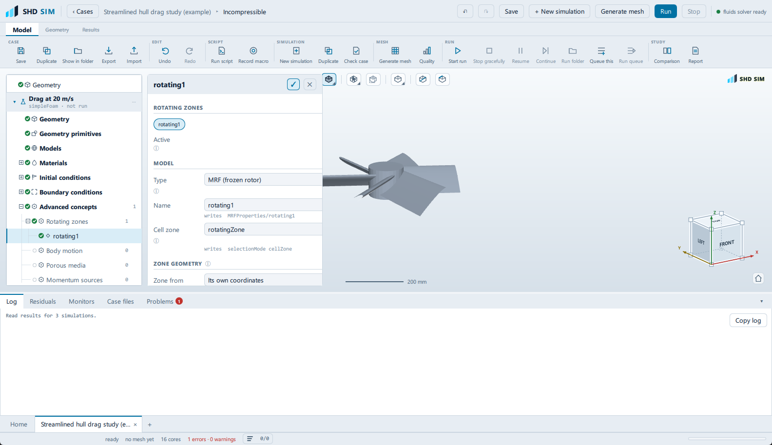
An item is created, gets its own node in the setup tree under Advanced concepts, and the application takes you to its editor.
The item
Active is on. Inactive concepts stay in the case but are written with
active no, which is a useful way to run the same case with and without the
rotation.
Type — set to MRF (frozen rotor).
Name — names the entry in MRFProperties.
Cell zone — the name of the cell zone this concept acts on. The zone is built from the geometry below.
Zone geometry
This is the section that does the work.
Shape offers box, cylinder and sphere, and the hint says what you
almost always want: "A rotating zone is almost always a cylinder about its own
axis."
Take cylinder and set:
- Radius — comfortably outside the blade tips, but inside the casing. A zone that clips the blades is wrong; a zone that touches the casing wall is also wrong, because the wall is stationary and the zone would try to spin it.
- Length — along the axis below, covering the rotor with clearance at both ends.
- Axis X, Axis Y, Axis Z — the rotation axis of the cylinder.
- The six min and max fields position the box the cylinder is centred on.
Fit to geometry gives you a starting zone sized from the case, which is easier to adjust than a set of numbers typed from nothing.
Rotor
Below the zone geometry is a Rotor section with a Rotor part picker —
the parts when the geometry has been split into them, the one body patch when
it has not — and a Fit zone to rotor button beside it, which builds a
cylinder about the axis a fifth larger than the rotor part in radius and length.
This is the cheap route to a correct zone. Naming the rotor part does three things at once: it sizes the zone around the blades rather than around a number you guessed, it adds a forces control on that part, and it points that control's centre of rotation and moment axis at the zone — which is the torque measurement step 8 sets up by hand. Refitting the zone afterwards moves the centre of rotation with it.
The zone is a set of cells, so it does not exist until the mesh does. The
pane says so: nothing here selects anything until there is a mesh. The
application runs topoSet after meshing to cut the zone out, and only then does
MRFProperties refer to something real.
One line in this pane says the zone is created "before meshing". It is not — the zone is cut from the mesh after it is generated, which is what the paragraph immediately below that line says and what the run pipeline does.
Rotation
Speed in rpm, and an Axis given as three components.
The sign of the axis sets the direction of rotation, and getting it backwards gives a machine that produces negative head with no error anywhere. Check it against the blade geometry before running: a pump whose blades sweep backwards relative to the rotation is a pump running in reverse.
5. Re-mesh
Press Generate mesh again after defining the zone.
The zone is cut by topoSet as part of the meshing pipeline, so a zone defined
after the last mesh does not exist in the mesh on disc yet. Skipping this is the
single most common way to get a case that runs and does not rotate: the solver
reads MRFProperties, looks for the cell zone, finds nothing, and the rotor
sits there.
6. Models, Materials
Models — Incompressible, Steady-state, SIMPLE, k-omega SST.
MRF adds Coriolis and centrifugal terms and can make convergence harder than the same case without rotation. If it fights you, the Robust preset under Numerics is the first thing to try, not a finer mesh.
Materials — set the working fluid. A pump in water and the same pump in air are different machines.
7. Boundary conditions
Select Boundary conditions.
The rotating zone is not a boundary condition and has no entry here. It is a volume, and it is configured entirely under Advanced concepts. If you find yourself looking for it in this pane you have the wrong mental model of what MRF is.
The rotor surface is a Wall with Wall motion at Stationary (no-slip). This is counter-intuitive and it is correct: inside the rotating frame the blade is stationary, and the frame is what rotates. The Rotating wall option under Wall motion, which takes a rotation rate in rad/s, is for a wall that spins within a stationary frame — a shaft passing through the domain, for instance — and using it on blades inside an MRF zone applies the rotation twice.
The casing is a Wall, stationary, and must lie outside the rotating zone.
Inlet and outlet as usual: a Velocity inlet and a Pressure outlet, or a flow rate driven from the inlet, depending on how the machine's operating point is defined.
8. Result control
Select Result control.
+ Forces and moments is the key one — "the same thing in newtons and newton-metres". Set its Patch to the rotor. The moment about the rotation axis is the shaft torque, and torque times angular velocity is the power the machine absorbs, which is half of what a pump curve is made of.
Turn off Moments about the model centre and give the Centre of rotation explicitly as the point the shaft passes through. The model centre is not the shaft centre except by coincidence, and a moment about the wrong point is not a torque. If you named a Rotor part in step 4, this control already exists and is already pointed at the zone axis; check it rather than adding a second one.
The other half of the pump curve is the head, so add:
- + Patch data with Operation set to areaAverage on
pat the inlet, and another at the outlet. The difference is the pressure rise. - + Flow rate through a patch for the volumetric or mass flow, which is the x-axis of the curve.
Add + y+ to confirm the blade wall treatment afterwards.
9. Run
Select Simulation runs — that is the node's name — and press Start run.
Watch Monitors rather than the residuals. MRF cases often reach a state where the residuals sit at a plateau while the torque is still climbing — because the swirl field is still developing through the domain — and stopping at the plateau gives a torque that is too low.
The convergence test is: torque flat, pressure rise flat, mass balance near
1. The run's own pane shows the mass balance as ṁ … out/in alongside the
coefficients.
If the run diverges immediately, the usual causes in order of likelihood are: a zone that clips a stationary wall, a rotation axis that does not match the cylinder axis, and a rotation speed entered in rad/s into a field asking for rpm.
10. Post-processing
Post-processing hangs under the run rather than beside the setup steps:
Simulation runs → <your run> → Post-processing, and it appears only once that
run has finished. Selecting it switches the ribbon to the Results tab.
Press Show results.
Forces and separation builds the surface pressure and the surface-flow pattern on the blades. The surface flow on a blade is where you see whether the loading is where the design intended it or whether the leading edge is stalled.
Wake and vortices shows what leaves the rotor — the tip vortices and the swirl in the downstream passage.
Then use Sample along a line under Plot over line, set across the
passage downstream of the rotor, on U. The swirl component in that profile is
the direct evidence that the rotation did something. A profile with no swirl
downstream of a rotor means the MRF zone is not active — go back and check
that the mesh was regenerated after the zone was defined.
11. Report
Select Report, under the same run, and keep Physics and materials on so the rotation speed is recorded, and Boundary patch data for the flow through each patch, which is the table the mass balance can be checked from.
What you should see
Swirl downstream of the rotor. A shaft torque that settled. A pressure rise across the machine with the sign you expect. A y+ on the blades inside the range your wall treatment needs.
Things that mean it is wrong:
- No swirl and no torque. The zone is not in the mesh. Regenerate the mesh after defining the zone.
- Negative head from a pump. The rotation axis sign is inverted.
- Torque far too high, and a run that struggles to converge. The zone probably includes stationary walls — check the cylinder radius against the casing.
- A result that changes when you move the zone boundary. The zone is too close to the blades, or the mesh across the interface is too coarse to carry the swirl. Both are real, and both are why the refinement region in step 3 is not optional.
What to try next
- Run a curve, not a point. Duplicate the simulation from its ⋯ menu, change the flow rate, and run it again. Several points give you the characteristic, and the Comparison node puts them side by side — see Mesh independence study for how that node works.
- Rotating frame (SRF) under Specialist in the wizard, if the whole domain rotates and there is no stationary part anywhere. It needs no zone and no interface, and its notApplicable list says exactly when it stops being valid: a stationary part anywhere in the domain, or rotor–stator interaction.
- Sliding mesh (AMI) on the same case, as a second simulation, if you need blade passing. Set Time dependency to Transient first.
- Momentum sources → Actuator disk under Advanced concepts if you do not need blade detail at all: thrust over a disk without meshing blades, which for a propeller in a hull-resistance study is often the right level of model and a small fraction of the cost.